
The following article describes the replacement of the front cover of the meter head, referred to as the front cover, on RMG TME 400 turbine gas meters.
This description applies equally to all device versions (-VM, -VC, -VMF, -VCF) in all nominal sizes and pressure ratings. Therefore, only the designation TME 400 is used throughout this document.
Please note that this description does not replace the applicable operating manual for the device. All precautionary and safety measures specified in the operating manual must be observed and followed accordingly.
- These documents can be found on our website at https://www.rmg.com.
TABLE OF CONTENTS
- 1. Safety instructions
- 2. Required tools and materials
- 3. Troubleshooting before replacing the front cover
- 5 Replacing the front cover
- 6. Contacting Technical Support
1. Safety instructions
As the front cover can be replaced during live operation without any need to switch off the meter, the following safety instructions must be observed without fail:
| DANGER |
Risk of explosion when replacing the front cover in a potentially explosive atmosphere! Replacing the front cover in a potentially explosive atmosphere poses an acute risk of explosion. This may result in serious injury or even death.
|
| NOTE |
Handling lead seals As replacing the front cover does not require any intervention in parts relevant to measurement technology, any existing calibration seals remain intact.
|
2. Required tools and materials
- 1.0 x 5.5 mm slotted screwdriver (suitable type for the housing screws used in the front cover)
- Large slotted screwdriver or coin to open the battery compartment cover
- Pin punch or small slotted screwdriver
- Replacement front cover, if the keypad is confirmed to be defective (available from RMG Service)
3. Troubleshooting before replacing the front cover
As the front cover and keypad are permanently bonded together during manufacture, they can only be replaced as a complete unit. It is therefore necessary to verify that the integrated keypad is actually defective before proceeding with the replacement.
- Check the TME 400 for the following fault symptoms:
- The device does not respond to keypresses.
- The device switches off briefly and then back on again when the batteries are removed and reinserted.
- If the keypad fault is confirmed, contact RMG Service to obtain a replacement front cover (email: service@rmg.com). Please provide the device serial number.
5 Replacing the front cover
- Loosen the screws on the front cover and then fold it open to the left (see fig. 1).
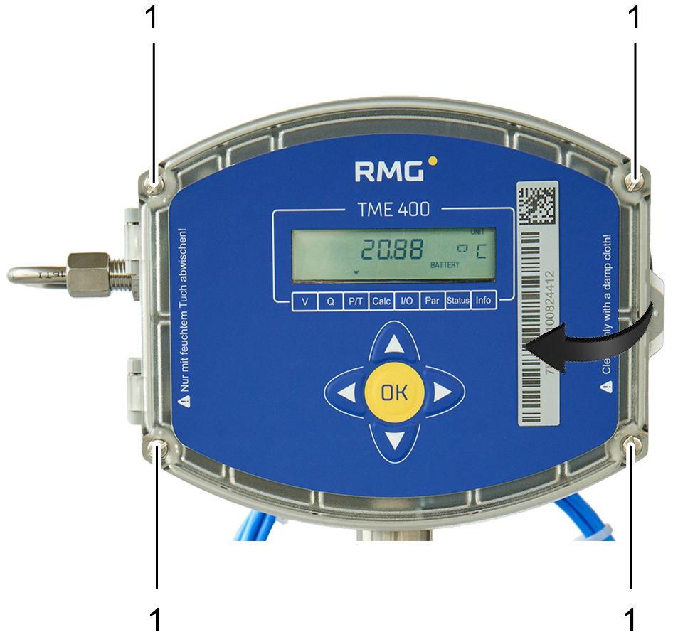
Fig. 1: Loosening the screws and opening the front cover
| No. | Designation |
| 1 | Screws for securing the front cover to the meter head housing |
2. If a power module (fig. 2, no. 1) is fitted, remove it carefully. To do so, pull the module straight out towards you without using any tools. The power module is simply plugged in, but the pins on the plug-in contacts are highly sensitive and may break if the module is pulled out at an angle or levered away from the main board (fig. 2, no. 2) using tools.
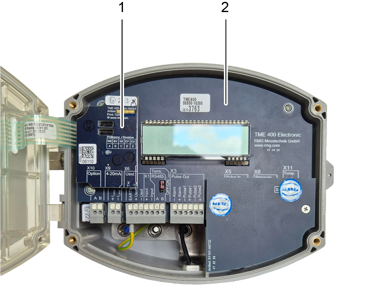
Fig. 2: Power module location
| No. | Designation | No. | Designation |
| 1 | Power module (fitted) | 2 | Main board |
3. The flat ribbon cable connector is located beneath the power module (see fig. 3, no. 2). Check that the connector is correctly inserted and that the flat ribbon cable (fig. 3, no. 1) shows no visible damage, in particular kinks or tears.
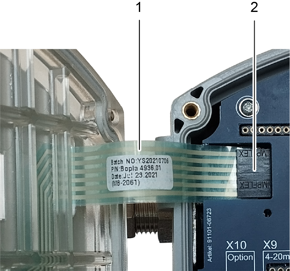
Fig. 3: Flat ribbon cable with connector
| No. | Designation | No. | Designation |
| 1 | Flat ribbon cable | 2 | Flat ribbon cable connector |
4. Carefully pull the flat ribbon cable connector out of the main board to the left. As the connector has no locking mechanism, this should be straightforward without any need for tools.
5, Close the front cover without screwing it shut.
6. Release the cover’s hinges to remove the front cover from the meter head. Using a pin punch, press the coiled spring pins out of the joints on both hinges. This can be done without applying significant force, provided that the cover is not misaligned. Do not use a hammer or similar tools under any circumstances. Take care to store the coiled spring pins carefully afterwards.
7. Remove the released front cover.
8. Position the replacement cover in the correct position, aligning the hinge holes of the cover and the housing with each other. Then press the coiled spring pins back into the holes. Ensure that the spring pins do not protrude on either side to guarantee a secure hold.
9. Open the front cover again.
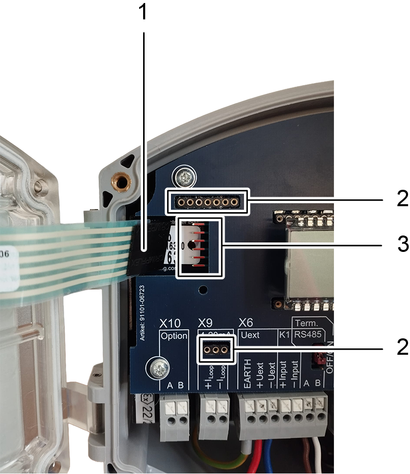
Fig. 4: Connectors on the main board
| No. | Designation | No. | Designation |
| 1 | Flat ribbon cable connector | 2 | Contact sockets for power module |
| 3 | Pins on the main board |
10. Now re-establish the connection between the keypad of the new front cover and the main board by very carefully plugging the flat ribbon cable connector onto the pins on the main board (fig. 4, no. 3). Ensure that the connector is sitting centrally on the pins and that the flat ribbon cable is lying flat and is not twisted.
11. If a power module was removed, reinsert it into the contact sockets on the main board (fig. 4, no. 2). Ensure that both rows of pins on the module are precisely aligned with the contact sockets on the main board to avoid damaging the power module pins.
12. Close the front cover and test whether the keypad is working and whether the meter can be woken from the power-saving mode with a keypress.
13. Reattach the front cover with four screws (see fig. 1, no. 1).
- The TME 400 is now fully operational again.
6. Contacting Technical Support
If you have any questions, please contact RMG´s Technical Support by emailing support@rmg.com or by visiting support.rmg.com.

Was this article helpful?
That’s Great!
Thank you for your feedback
Sorry! We couldn't be helpful
Thank you for your feedback
Feedback sent
We appreciate your effort and will try to fix the article